Crew Safety Induction

This induction is for all crew working for EPS installing our products and services across the UK.

Language Options

Section 1

General Safety Information

Working on Client Sites

Site Inductions

  • Before working on each site, you must complete a site-specific induction.
  • If you have any questions after the induction, please speak to your crew boss.

Behaviour

  • Please be mindful of your behaviour when on site, you represent EPS and our reputation with our clients.
  • Be polite and avoid the use of foul language, especially when around others.

Our Safety

Yours, ours, and everyone else’s safety

  • Be aware of those around you, especially work colleagues, and what you are doing. If you need to pause for 30 seconds until someone gets out of the way, then that’s ok.
  • If something isn’t right, doesn’t look right, or you think something is unsafe, say something. If you need to say STOP, get the crew boss involved to make an assessment and ensure that it is safe to continue.

If you’re not sure

  • If you’re not sure how to do something or it seems unsafe, ask you’re crew boss. Do not attempt to do it without following the instructions; some of the equipment can cause harm if not properly installed, as outlined in the procedures further on in this induction.
  • Always ask if you’re unsure; there’s no such thing as a stupid question when it comes to safety.

Alcohol and Illegal Drugs

Whilst on-site there is a ZERO tolerance for being under the influence of alcohol or illegal drugs.

  • If you are suspected of being under the influence of either you will be removed from the site immediately and may face disciplinary action.

Section 2

Personal Protective Equipment (PPE)

PPE

Minimum PPE to be worn whilst on site

  • Hi -Viz vest;
  • Toe protective footwear, ideally boots that provide ankle support;
  • Work gloves when installing and dismantling products.

Hi Visibility Clothing

Toe Protection

Steel/ Composite Toe Protective Footwear

  • As a minimum, you should wear toe protective footwear when on site, this includes any standby periods whilst onsite during an event.

Work Gloves

Don’t forget your gloves.

  • Ensure you have suitable work gloves and wear them at all times. They help keep your hands clean and can prevent cuts and scrapes when handling the products.

Manual Handling

T-I-L-E

T stands for task. Think about the nature of the manual handling task itself:

  • Does it involve lifting, lowering, carrying, pushing, or pulling?
  • How may these actions affect your health and safety?
  • Does the task contain any strenuous movements, long distances, uneven weight distributions, or repetitive movements?

I stands for individual. Think about who will be carrying out the manual handling task:

  • How strong, fit, or capable is the individual?
  • Are they suitable for manual handling on their own?
  • Do they require support to complete the task?

L stands for load. Think about the object or person being moved:

  • Is the weight unusually heavy, bulky, difficult to hold, or unstable?

E stands for environment. Think about where the load is being moved from and to:

    • Is there a lack of space?
    • Is the flooring wet or irregular?
    • Is there enough lighting?
    • Are there any potential trip hazards?

  • Keep your back straight

  • Bend at the knees

  • Lift within your limits

  • Don’t bend and lift with your back

  • Don’t lift things that are too heavy, ask for help

  • Don’t rush the lift

Section 4

Supatrac Flooring

Weight per pre formed Sheet = 47.1 kg

❗️MINIMUM TWO PERSON LIFT

PPE required

  • A Hi-Viz vest or Jacket

  • Safety Boots (lace up with ankle support)

  • Gloves

Installation

Please watch this video below which shows you the Supertrac and how to handle it.

Installation
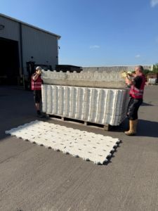
  • Sandbags or packing will be used where surface levels differ significantly or areas of soft ground are discovered. Where the customer specifies or where eps insists, a protective membrane is to be laid underneath the Supatrac to minimise the environmental impact of the installation, and aid in the installation/recovery of the product.
  • Each pallet / stillage is placed at a convenient location for the crew to install by hand. Supatrac is pre-connected in sheets of 15, forming an area of 3.16m2 (5 by 3) and is installed by a minimum of two operatives.
  • The Supatrac can be installed in various configurations, as walkways, or as pads to cover large areas of ground. Each panel is designed to clip into its neighbour(s) by using the built in T shaped connectors. Where the ground is particularly uneven, connections can be secured by use of a retaining clip secured using a small hammer.
  • The installation is completed by starting on the left hand side working methodically to the right. This ensures the female connection points are readily available for the male connections to be fitted to.
  • Each pre-formed sheet of 15 pieces is positioned by two operatives holding the sheets at each end. As the sheets are lifted from the stack, they are lifted so that the short end is folded into a U shape. This reduces the stresses on the joints.
  • The long edge is presented to the previously laid sheet so that the connectors are aligned. The sheet is then lowered to the floor and by applying a little pressure along the joint, the sheet is secured into place.
  • The supa trac sheets should be positioned squarely against the next as described above, if you start to feel resistance in the installation then you will encounter problems.
  • Ramps where required are positioned at the outer perimeter of the installation and secured into position using the same method as above. Retaining clips should be used to secure ramps into position.
  • All clips should be a different colour in order to identify the joints.

Recovery

Recovery

  • Recovery is a reverse process of the installation.
  • Clips are removed and each pre-connected Supatrac sheet is lifted and uncoupled from its neighbour(s).
  • Supatrac is placed on pallets / stillages neatly with all connectors aligned as they are recovered.
  • For full pallets / stillages the recovery crew use a bander and banding or strap to secure the stack. Each pallet is double banded or double strapped as a minimum.
  • Any sandbags or packing that has been used for ground levelling is collected and placed in stillages for transport. Protective underlay is rolled up, recovered and loaded onto the recovery vehicle.
  • Any damaged sheets are segregated from the main stockpile for inspection by the client (if appropriate).

Section 5

ArmorDeck Flooring

Weight per Tile = 18.2 kg

PPE required

  • A Hi-Viz vest or Jacket

  • Safety Boots (lace up with ankle support)

  • Gloves

Installation

Please watch this video below which shows you the ArmorDeck and how to handle it.

Installation

  • Sandbags or packing will be used where surface levels differ significantly or areas of soft ground are discovered.
  • Where the customer specifies or where eps insists, a protective membrane is to be laid underneath the ArmorDeck to minimise the environmental impact of the installation, and aid in the installation/recovery of the product.
  • Each pallet / stillage is placed at a convenient location for the crew to install by hand. ArmorDeck is installed as an individual tile and is installed by a minimum of two operatives.
  • The ArmourDeck can be installed in various configurations, as walkways, or as pads to cover large areas of ground. Each panel is designed to clip into its neighbour(s) by using the built-in cam lock connectors. Where the ground is particularly uneven, packing timbers/sandbags are to be used.
  • The installation is started by starting on the left-hand side working methodically to the right. This ensures the female side of the tile is offered up for the male side
  • Each tile is positioned by two operatives holding the tile at each end. As the tiles are lifted from the pallet, they are lifted so that the male/female ends drop straight into position.
  • An operative with an ArmourDeck Key will lock in position the tiles as they are positioned.
  • The ArmorDeck tiles should be positioned squarely against the next as described above, if you start to feel resistance in the installation then you will encounter problems as you progress with the install, stop the install and rectify the problem.
  • Ramps where required are positioned at the outer perimeter of the installation and secured into position using the same method as above.

Recovery

Recovery

  • Recovery is a reverse process of the installation.
  • Unlock the cam locks prior to the uplift of the tiles, work along in lines to ensure that no cam locks are left closed.
  • ArmorDeck is placed on pallets / stillages neatly with all connectors aligned as they are recovered.
  • For full pallets / stillages the recovery crew use a bander and banding or strap to secure the stack. Each pallet is double banded or double strapped as a minimum.
  • Any sandbags or packing that has been used for ground levelling is collected and placed in stillages for transport. Protective underlay is rolled up, recovered and loaded onto the recovery vehicle.
  • Any damaged sheets are segregated from the main stockpile for inspection by the client (if appropriate).

Section 6

GIGS Barrier

Weight per Barrier = 34 – 40 kg

❗️MINIMUM TWO PERSON LIFT

PPE required

  • A Hi-Viz vest or Jacket

  • Safety Boots (lace up with ankle support)

  • Gloves

Installation

Please watch this video below which shows you the Gig Barrier and how to handle it.

Installation

  • On-site, the stillages can be transported by forklift truck or pushed if the ground allows.
  • Two men lift out each section and lay it flat on the ground in the appropriate position, depending on the configuration required.
  • The top of the barrier is lifted to unfold the barrier.
  • Note – Care should be taken when positioning the hands to avoid trapping fingers.
  • As the upright section of the barrier reaches vertical, the bottom edge is tapped forward to lock the step and barrier into the working position. These bottom lugs will be positioned under the front foot plate.
  • The barriers are slid together, ensuring the top and front locking pins connect, and a fixing bolt is inserted along the bottom edge. A battery-powered wrench or spanner is used to tighten the bolts.
  • Once complete joints are taped with Gaffer tape to ensure no pinch points along the barrier.
  • All accessories, i.e. angle sections, are fitted using the same method as above.
  • Should the installation area be uneven then packing timbers are to be used, along with anti-slip rubber matting on certain floors i.e. stadium concrete flooring.

Recovery

Recovery

  • All bolts are removed using the battery-powered wrench or spanner, and the barriers are pulled apart.
  • Remove all tape from the barriers, and sweep/clean the debris from the barrier where possible.
  • The standing platform is lifted out of the locked position, and the bottom of the vertical section is slid towards the rear of the barrier so that it is folded flat. Note: Hold the barrier by the frame as holding the bracings could lead to serious injury.
  • Use the correct lifting method, move the barrier dolly along the barrier line where possible, and avoid carrying the barrier long distances.
  • The two crew members lift the barrier and place it in the stillage for transportation. Barriers will only fit into the stillage one way, so do not force them into the stillage, as this may damage the barrier and injure the crew members.

Section 7

RELLY + Vacuum Attachment

The Relly Machine is only to be operated by trained EPS Staff. This method statement is for crew operating forks and installing panels using hand tools, and bolts.

PPE required

  • A Hi-Viz vest or Jacket

  • Safety Boots (lace up with ankle support)

  • Hard Hat

    List Content goes here

  • Gloves

  • Gloves

Installation

Installation

  • The Relly is manoeuvred into position where the installation begins, and the installation team are to agree on a deployment method before installation. (Communication methods for manoeuvring are to be pre-agreed)
  • The role of the Relly operative is to ensure that all aspects of the operation are controlled.
  • The Relly will either be fed by a fork truck to the installation area or pick up the individual panels at the pre-agreed-upon stockpile.
  • The Relly is to lift a maximum of 1 panel. The load is lifted a few inches to test it for security and to check that the lifting device has engaged. Ensure the arm is under the load in the correct position. Once this has been established, the load is manoeuvred into position adjacent to the area for the installation using the Relly. Communication is to be maintained at all times.
  • The vacuum must be located on a single plank.
  • The Relly takes a single panel from this working pile/ FLT, manoeuvres the machine into position, and places the trackway panel on the ground in the correct position for the start of the installation.
  • The two-man team will work alongside the Reilly and its operator, maintaining a safe distance until the machine is stationary. Once stationary, the Trackway panel is lowered into position, where the two-man team will guide and locate the panel using the podger / panel locating pin provided for the panel installation.
  • The 2-man team will use the podger locating pin to guide the panel against the adjacent panel. No force should be needed as the machine does the manoeuvring. Ensure the panel has a nut and fish plate in position and is ready for the next panel.
  • The Reilly and its operatives will position the panel and, once positioned correctly, will release the panel and reverse to start the process all over again
  • The two-man team will use an impact drill to tighten the bolts and nuts. Due to the close proximity of the machines and personnel, all operations and manoeuvres will be structured and measured. The team will be experienced and fully aware of the installation process.
  • Successive panels are lifted using the same technique; each one is positioned up to the previously laid panel using the Relly to manoeuvre it into place. Each panel is secured to the previous panel using nuts, bolts and washers with an impact wrench.
  • This process is repeated until the installation is complete.

RELLY and Vacuum Attachement

  • This can be seen in the images below on the right-hand side. The vacuum attachment attaches to a Tracway panel through suction and transports it to where it is needed, then is installed by the crew.

Recovery

Recovery

  • The recovery of the Trackway is a reverse of the installation, applying all the same principles but in reverse.
  • The individual panels are unbolted and bagged/recycled by the 2 man Relly team.
  • Recovery is the reverse of the installation method.
  • Lift 1 panel at a time, ensuring that the suction attachment works correctly and no debris is situated on the trackway panels. Communicate and agree stockpile area or position of the feeder FLT to be agreed before starting.
  • Please refer to the relevant RAMs for loading /unloading the delivery vehicle.
  • If a geotextile membrane is used, it will need to be recovered once the trackway is lifted and, where possible, returned to EPS UK for recycling.
  • Should sandbags or packing have been used for ground levelling, then this is to be collected and placed in stillages for transport. Ensure the sight is left as found. All litter and debris to be removed

Induction Confirmation

EPS Crew Safety Induction 2025

Thank you for taking the time to complete this induction. If you have any questions or queries please contact your line manager.

  • EPS or the crewing company you work for.
  • List sites or main site you will be working at.
  • Clear Signature